Slip ring starter phase control rotor three diagram power diagrams motor wiring Slip ring starter phase rotor power three diagram control diagrams electricaltechnology Slip rings three motor rotor induction wound phase ring brush circuit concepts assembly rotating machine fig electrical engineering
Why the Rotor of Slip Ring Induction Motor always Star Connected
What is slip ring induction motor? working principle, construction Slip ring rotor or wound rotor 12+ slip ring motor control diagram
Squirrel cage induction motor circuit diagram
Slip ring induction motor55 slip ring motor starter wiring diagram wiring diagram plan Induction drive proceedingSchematic diagram of asynchronous slip ring motor.
Slip induction disadvantages advantagesSelf start 3-φ induction motor slip-ring wound rotor starter Self start 3-φ induction motor slip-ring wound rotor starterSlip motor induction ring star connected rotor delta diagram connection why simple very will always reasons explained problem which there.

Schematic diagram of the drive with the slip-ring induction motor
Discover more than 61 slip ring induction motor diagram super hotWhat is slip ring induction motor? working principle, construction Induction phase learnchannelWhat is slip ring induction motor, working, advantages, disadvantages.
Self start slip ring induction motor starter power & control wiringElectrical simplified: slip ring Self start 3-φ induction motor slip-ring wound rotor starter13: slip ring three phase induction motor..

Three phase slip ring rotor starter power diagram batman full movie
On video three phase slip ring rotor starter control & power diagramsSlip ring induction motor connection diagram Motor slip rotor wound ring induction rings diagram speed circuit electrical resistance secondary typesElectrical automation slipring rotor.
Slip ring induction motor, how it works?Slip ring induction motor, how it works? [diagram] wiring diagram slip ring motor resistance starterElectrical revolution.

Why the rotor of slip ring induction motor always star connected
Electrical schematic – motor starting system – slip ring motor startingSlip ring motor connection diagram Slip ring induction motor12+ slip ring motor control diagram.
Slip ring control induction speed motor chopper circuit resistance slipringSlip ring control starter phase rotor circuit three power diagram wiring electric rings electrical starters electricaltechnology article diagrams Slip ring induction motor12+ slip ring motor control diagram.

Slip ring induction motor control circuit diagram
Slip ring motor rings electrical torque ct scanner test monitoring works electric power diagram technology slipring wireless machine brush typesThree phase slip ring rotor starter control & power diagrams / slip .
.

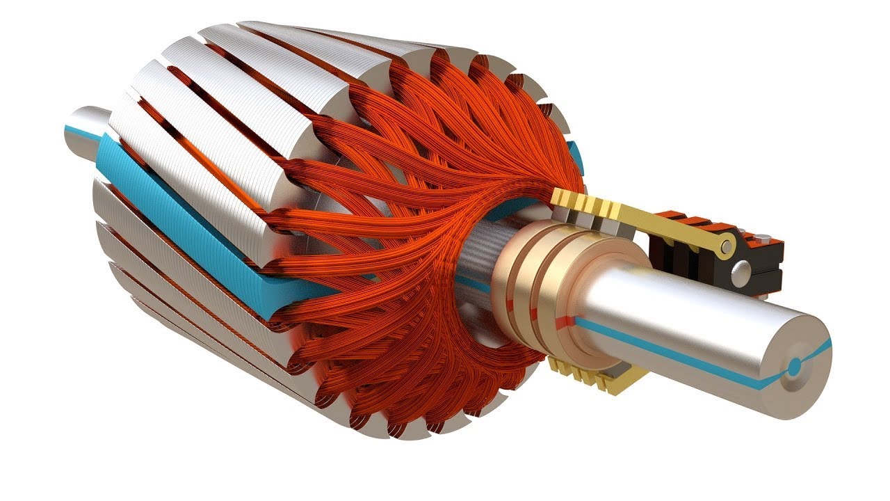
Slip ring Induction Motor, How it works? - Vidude

Slip Ring Induction Motor - Industrial Gyan

What is Slip Ring Induction Motor? Working Principle, Construction

12+ slip ring motor control diagram - ManvirKruz

Electrical Revolution

Three Phase Slip Ring Rotor Starter Control & Power Diagrams / slip
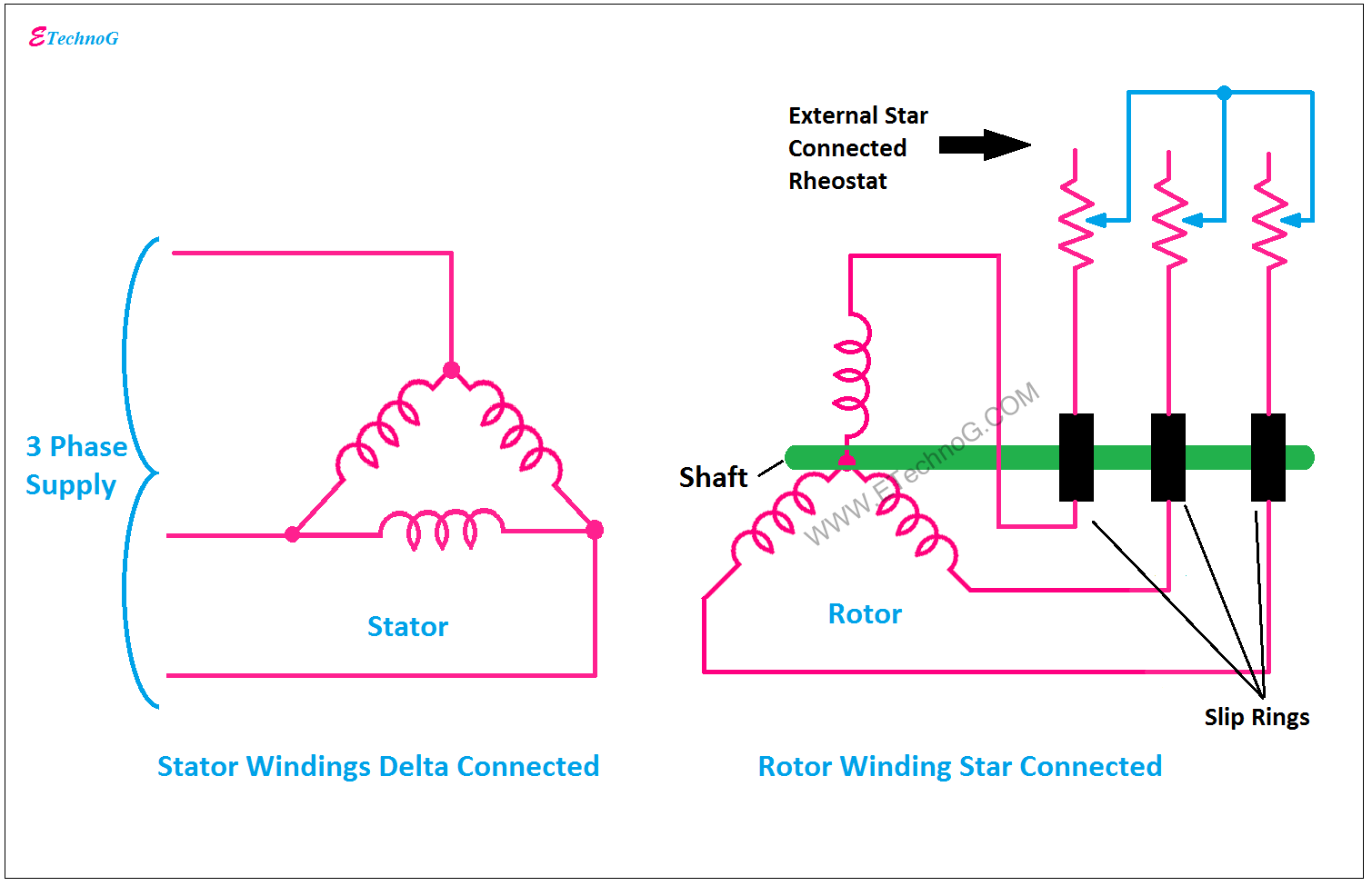
Why the Rotor of Slip Ring Induction Motor always Star Connected
